4. Hardware Setup, Calibration & Diagnostics
Here you will learn how to physically connect your pen plotter to your computer, configure serial interface parameters on the control panel and in the Device Settings dialog, test communication using the built-in diagnostic probe tool, and run the official calibration plot.
1. Physical Connection & Cabling
Classic plotters utilize RS-232 serial interfaces (typically 25-pin DB-25 or 9-pin DB-9 connectors). Modern computers usually lack native COM ports, requiring a USB-to-serial adapter.
Recommended USB-to-Serial Adapters
- Chipset: Use adapters with genuine FTDI (e.g. FT232R, FT2232) or Silicon Labs (CP2102) chipsets.
- Caution: Inexpensive clone adapters lacking proper hardware RTS/CTS flow control will cause buffer overruns and data loss on larger vector drawings.
Null-Modem Cabling with Genuine Hardware Handshake
Reliable communication strictly requires a full-handshake null-modem (crossover) cable:
| Signal | PC Side (DB-9 Female) | Plotter Side (DB-25 Male) | Plotter Side (DB-9 Male) | Description |
|---|---|---|---|---|
| RxD (Receive) | Pin 2 | Pin 2 (TxD) | Pin 3 (TxD) | Receive data line |
| TxD (Transmit) | Pin 3 | Pin 3 (RxD) | Pin 2 (RxD) | Transmit data line |
| GND (Ground) | Pin 5 | Pin 7 (GND) | Pin 5 (GND) | Signal ground |
| RTS (Request to Send) | Pin 7 | Pin 5 (CTS) | Pin 8 (CTS) | PC indicates readiness |
| CTS (Clear to Send) | Pin 8 | Pin 4 (RTS) | Pin 7 (RTS) | Plotter throttles data flow (Handshake) |
| DTR (Data Terminal Ready) | Pin 4 | Pin 6 (DSR) | Pin 6 (DSR) | Operational readiness |
| DSR (Data Set Ready) | Pin 6 | Pin 20 (DTR) | Pin 4 (DTR) | Operational readiness |
Important: A simple 3-wire connection (only TxD, RxD, GND) without RTS/CTS is unreliable on pen plotters because the plotter must be able to pause the computer during complex mechanical movements.
Alternative: TCP / Ethernet Device Servers
Instead of a direct USB cable, you can use serial-to-Ethernet converters (e.g. Moxa NPort, USR-TCP232) or a Raspberry Pi running socat. LINTO natively supports TCP network sockets via tcp://<IP-Address>:<Port> (e.g. tcp://192.168.1.150:4001).
2. Control Panel & DIP Switch Setup (Mutoh XP-500 Example)
Configure the following settings on your plotter's front control panel or DIP switches:
- Emulation: HP-7585B or MH-GL.
- Baud Rate:
19200baud (or9600baud for very long cables). - Data Format:
8data bits,Noneparity,1stop bit (8N1). - Handshake / Flow Control: Hardware (RTS/CTS). XON/XOFF must be disabled.
- Margin Profile: EXP (Expanded).
- Paper Loading: After loading the paper, the optical sensor detects sheet edges automatically.
3. Device Settings Dialog
Open Device → Settings... from the menu or top toolbar to configure your plotter in LINTO:
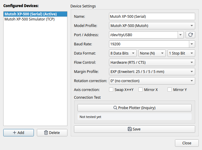
- Plotter List: Displays all configured devices.
- [ New Device ]: Adds a new device configuration.
- Per-Device Settings:
- Display Name: Custom label (e.g.
Mutoh XP-500 StudioorRoland DXY-1150 Flatbed). - Device Profile: Base hardware model selected from the 25+ bundled profiles (e.g.
mutoh_xp500,roland_dxy,hpgl_generic). - Port & Baud Rate: Serial port (e.g.
/dev/ttyUSB0) or network address (tcp://127.0.0.1:9999), baud rate, parity, and flow control. - Margin Profile: Default margin configuration for the device.
Note
To learn how to integrate additional plotter models, write custom YAML device profiles, or import drivers from Inkcut, see Chapter 5: Adding Custom Plotter Models & Device Profiles.
4. Hardware Diagnostics with tools/xp500_probe.py
LINTO includes a standalone terminal diagnostic tool to verify the serial lines and inspect raw responses at the byte level:
# Probing via USB-Serial:
python3 tools/xp500_probe.py /dev/ttyUSB0

# Probing with custom baud rate and detailed ESC sequences:
python3 tools/xp500_probe.py /dev/ttyUSB0 --baudrate 19200 --esc

# Probing via network / TCP server:
python3 tools/xp500_probe.py tcp://127.0.0.1:9999
Typical Output on a Successful Connection:
=================================================================
  LINTO – Mutoh XP-500 Hardware-Diagnose (AP0)
=================================================================
Ziel:      /dev/ttyS5
Baudrate:  19200
Timeout:   0.6 s
-----------------------------------------------------------------
Verbindung: Serieller Port geöffnet. Signals: CTS=True, DSR=True

Abfrage-Ergebnisse (siehe docs/devices/mutoh-xp500/testplan.md):
-----------------------------------------------------------------
OI;      | Modell-Identifikation (Standard) | 7585B
OF;      | Zeicheneinheit (Units/mm)      | 40,40
OH;      | Plottbereich / Hard-Clip       | -3678,-5692,3679,5692
OS;      | Statusbyte                     | 26
OE;      | Fehlerstatus (HP-GL)           | 0
OA;      | Aktuelle Position & Stift      | -3077,-5092,0
OT;      | Stiftkarussell-Status          | 1,0
OO;      | Optionen                       | 0,1,0,0,1,1,0,1
ESC.A    | ESC.A (Erweiterte ID)          | 7585B
ESC.L    | ESC.L (Puffergröße)            | 1024
ESC.B    | ESC.B (Freier Puffer)          | 1024
ESC.O    | ESC.O (Erweiterter Status)     | 392
ESC.E    | ESC.E (Erweiterter Fehler)     | 0
-----------------------------------------------------------------

Auswertung:
• Modell:        7585B
• Auflösung:     40.0 Units/mm (Schrittweite: 0.0250 mm)
• Hard-Clip:     X: [-3678, 3679], Y: [-5692, 5692] Units
• Abmessungen:   183.9 × 284.6 mm (Plottbarer Bereich)
• Erkanntes Blatt: DIN A4
• Puffer:        Gesamt: 1024 Bytes, Frei: 1024 Bytes
=================================================================
If a timeout occurs or CTS=False is reported, check your null-modem cable, the settings on the plotter control panel (protocol/handshake), and the operating system setup instructions below.
5. Operating System Setup & Troubleshooting (RS-232)
Linux
On Linux, serial interfaces are exposed as device nodes under /dev/. Depending on your hardware, there are several common pitfalls related to permissions, background services, or hardware interrupts.
1. Identifying the Right Port Name (/dev/ttyUSB* vs. /dev/ttyS*)
- USB-to-Serial Adapters (FTDI, Silicon Labs CP210x, Prolific PL2303, CH340) appear as
/dev/ttyUSB0,/dev/ttyUSB1, etc. (occasionally/dev/ttyACM0). - Onboard RS-232 & PCIe Serial Cards (16550A-compatible UARTs) appear as
/dev/ttyS0,/dev/ttyS1, etc. Because kernel drivers typically reserve/dev/ttyS0through/dev/ttyS3for motherboard headers, add-in PCIe cards often receive higher numbers such as/dev/ttyS4and/dev/ttyS5.
Use dmesg to inspect which serial ports the kernel detected at boot or when plugging in an adapter:
ttyS0) and a 2-port PCIe card (ttyS4, ttyS5):
[    0.702046] serial8250: ttyS0 at I/O 0x3f8 (irq = 4, base_baud = 115200) is a 16550A
[    0.704314] 0000:04:00.0: ttyS4 at I/O 0xe010 (irq = 41, base_baud = 115200) is a 16550A
[    0.704696] 0000:04:00.1: ttyS5 at I/O 0xe000 (irq = 42, base_baud = 115200) is a 16550A
2. Permission Denied (Errno 13: Permission denied)
By default, standard Linux user accounts do not have direct read/write access to /dev/ttyS* or /dev/ttyUSB*. Serial device nodes belong to the dialout group (Debian, Ubuntu, Linux Mint, Fedora, openSUSE) or uucp (Arch Linux, Manjaro).
- Check which group owns the port:
-
Add your user account permanently to the
dialoutgroup:[!IMPORTANT] Group membership changes on Linux only take effect after you log out of your graphical desktop session completely and log back in (or reboot).
-
Immediate workaround without logging out (for the current session): If you do not want to log out right away, you can grant your user temporary read/write access until the next reboot:
3. PCIe Serial Cards & Interrupt Issues (No irq handler / Timeout)
When using add-in PCIe RS-232 expansion cards (such as cards based on the common ASIX AX99100 chip [125b:9100], MosChip MCS99xx, or WCH CH382), the generic Linux kernel driver (8250_pci) may create /dev/ttyS4 / /dev/ttyS5 and read status lines (CTS=True, DSR=True) properly, yet every query or data transfer fails with a timeout.
- Typical Symptom: When accessing the port, the system log (
journalctl -kfordmesg) prints a kernel message such as: - Cause: Hardware interrupt routing (MSI/APIC) between the PCIe card and the
8250_pcidriver fails. Although the UART receives the plotter's reply into its hardware FIFO, it cannot trigger a CPU interrupt to notify the kernel. - Workaround (
setserialPolling Mode): By setting the serial port's IRQ to0usingsetserial, the Linux kernel bypasses hardware interrupts for that port and switches to reliable timer-based polling: - Making the setting persistent across reboots (udev rule):
Because
setserialsettings reset on reboot, you can automate them by creating/etc/udev/rules.d/99-serial-polling.rules:
4. Common Conflicts with USB-to-Serial Adapters (brltty & ModemManager)
brlttyhijacking USB adapters: Many Linux distributions (Ubuntu, Debian, Fedora) ship with thebrlttyBraille display daemon enabled by default. Its udev rules mistakenly identify some USB-to-serial adapters (especially FTDI and CH340) as Braille displays and disconnect/dev/ttyUSB0seconds after plugging it in (dmesgshowsinterface 0 claimed by ftdi_sio while 'brltty' sets config #1/ttyUSB0: now disconnected).- Fix (if you do not use a Braille display): Disable or uninstall
brltty: ModemManagerprobing ports withATcommands: Immediately after plugging in a USB-to-serial adapter,ModemManagermay probe the port for a few seconds to check if it is a cellular modem. Wait 5–10 seconds after plugging in the USB adapter, or power on the plotter after connecting the adapter soATprobe strings do not trigger an HP-GL syntax error on the plotter.
5. Quick Manual Console Test (stty & cat)
To test whether the serial port, cable, and plotter communicate at the OS level independently of Python or LINTO, you can configure and send data directly from a terminal (19200 baud, 8N1, crtscts hardware flow control):
macOS
- Device Names: USB-to-serial adapters appear twice under
/dev/on macOS—as/dev/tty.usbserial-*and/dev/cu.usbserial-*. Always prefer the/dev/cu.*(Call-Up / Call-Out) device in LINTO, because/dev/tty.*waits for the hardware Data Carrier Detect (DCD) line and may block when opening. - (Additional macOS-specific notes will be added in a future update.)
Windows
- Device Names: On Windows, serial ports are addressed as
COM1,COM2,COM3, etc. You can check which COM port number was assigned to your USB-to-serial adapter or PCIe card in Device Manager under Ports (COM & LPT). - (Additional Windows-specific notes will be added in a future update.)
6. The Calibration Plot (Accuracy, Margins, Pens & Backlash)
Pre-compiled calibration patterns for DIN A4 and DIN A3 are located in src/linto/resources/:
* src/linto/resources/calibration_plot_a3.svg / .hpgl
* src/linto/resources/calibration_plot_a4.svg / .hpgl
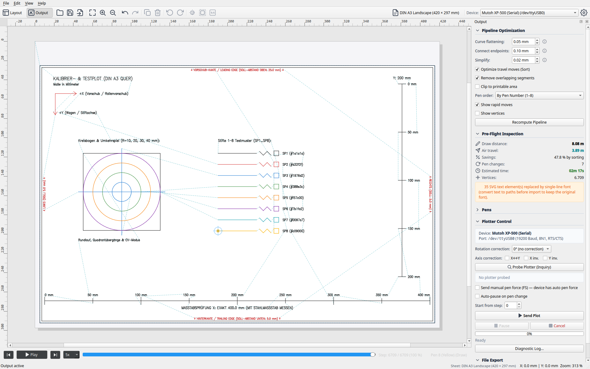
Calibration Features & Verification Criteria:
- Orientation Arrows (+X / +Y) & Edge Markers:
- An arrow marked
+Yand textTOP / LEADING EDGEis drawn at the feed edge. - Check: Was the text drawn upside-down or mirrored? If so, adjust
invert_x,invert_y, orrotation_degin the device profile. - Precision Measurement Line (400 mm for A3 / 200 mm for A4):
- A continuous measurement line with precise end ticks.
- Check: Measure the drawn line with a quality steel ruler.
- If the line measures exactly 400.0 mm, stepper resolution is calibrated at 40.0 units/mm. Any variance can be fine-tuned via
units_per_mmin the profile. - Outer Hard-Clip Border:
- Traces a rectangle along the plotter's maximum printable limits.
- Check: Are all 4 borders drawn cleanly without the pen running over pinch rollers or the carriage hitting mechanical limits?
- 8-Pen Matrix:
- 8 labeled test boxes with colored hatch fills.
- Check: Does the pen carousel change each pen smoothly? Do pen caps seal tightly?
- Concentric Circles & Square-in-Circle (Backlash Check):
- Concentric circles enclosing a centered square.
- Check:
- Do circle start and endpoints align perfectly?
- Are circles round or egg-shaped/elliptical?
- Quadrant shifts indicate mechanical backlash in drive belts or pinch wheels.